Step 3. Attaching the Ledger Board to the House
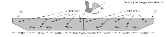
Starting at one end, prepare the ledger board for the joist hangers by measuring 250mm and marking with a pen on the lower edge of the ledger board. this will be where the first 'outside wall' of the first joise hanger should be positioned. Measure, from this mark, another 40mm and mark again. 40mm is the width of the joist hanger and represents where the other side of the joist hanger will be. Then, from this second mark, measure a further 680mm and mark. This is where the first outside wall of the second joist hanger should be sited. Continue this process for all the joist hangers and you will be left with the same 250mm length at the other end of the ledger board making the joist hanger positions symetrical.
Next, you can either screw in and fix the joist hangers, using the 25mm non recessed wood screws provided, in their pre-marked positions on the ledger board or, if you prefer, attach the joist hangers to the non-decorated end of the cross rafters as detailed in Step 5. If you do attach the joist hangers to the ledger board, please make sure that the walls of the hangers are completely straight. As they are 'nested' together for packaging purposes, the walls can become 'splayed' out a touch, if this is the case, gently squeeze togther the side walls until they become vertical.
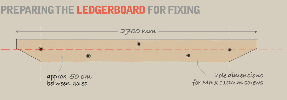
Fig 10 above shows a picture of the ledger board and the suggested fixing holes and spacings that you should pre-drill. We recommend using a zig-zag pattern, avoiding the 'marked up' hanger positions, with an approximate 500mm gap between fixings. This will provide a firm footing and will be more than enough to maintain the position and shape of the Ledger Board and prevent it warping over time. The ledger board fixings also offer a secure base for the rafter beams and are strong enough to carry the weight of any climbing plants that are grown up the structure. Pre-drill the pilot holes, which helps prevent the wood from splitting, using a 3mm wood bit.
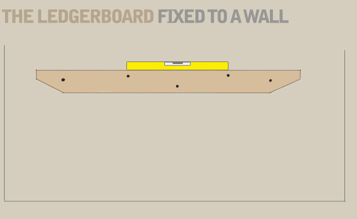
Once you have prepared your ledger board the next step is to mark the wall ready for drilling so that the ledger board can be attached. See Fig 11. You might find the task easier to ask for an extra pair of hands to help secure it firmly against the wall. It is important at this stage to make sure that the ledger board aligns perfectly with the position of the first post fixing support. So, taking the piece of string on the ground that has marked out the position of the first post support as your cue, take a plumb line (or another piece of string with a weight attached to the end) and position it exactly in the middle of the first 40mm gap where the first joist hanger will be positioned ensuring that it is perfectly verticle from the ground.
Offer the ledger board up to the wall making sure that the bottom edge is exactly 2400mm from the ground and when it is centered and squared with the plumb line in the middle of the first 40mm joist hanger gap, use a pencil to mark a line on the wall where the end of the ledger board rests. This mark is your starting point (use a spirit level here to ensure the ledger board is completely horizontal) and taking a drill with a small pilot masonry bit (3mm), drill through the ledger board holes and into the wall to a depth of half an inch or so. Continue to do this with all of the holes that you have made in the ledger board. Once done, take the ledger board down and deepen the holes in the wall by a further 50mm using the same 3mm pilot masonry bit.
Next, widen the holes using an 8mm masonry drill and clean out any dust that has gathered there and insert the wall plugs provided into the holes. If any of the plugs prove stubborn, take a small hammer and gently tap them into place so that they end up flush with the face of the wall.
If you attach anything to the brick or stone of an outside wall water can become trapped and soak into the surface which can lead to a brown stain running down the wall where the attachment has been fixed. If this occurs, the stain is particularly difficult to remove and looks a bit of an eyesore. Therefore, it is important to follow the method below to prevent this staining from happening. By using the spacers provided, it creates a gap between the ledger board and the wall itself which allows air to flow and helps the surfaces to fully dry out after rainy days.
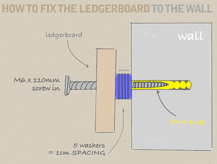
After you have drilled the holes in the wall, push the screws through the ledger board and spacers (see Fig 12) lining them up with the plugs in the wall and screw them in tight ensuring a firm attachment. A great tip here is to 'cap' the end of the screw, after it has been pushed through the ledger board and spacers, with a small bit of blutack or selotape, which prevents the spacers from falling off the screw as you offer the ledger board up to the wall for fixing.
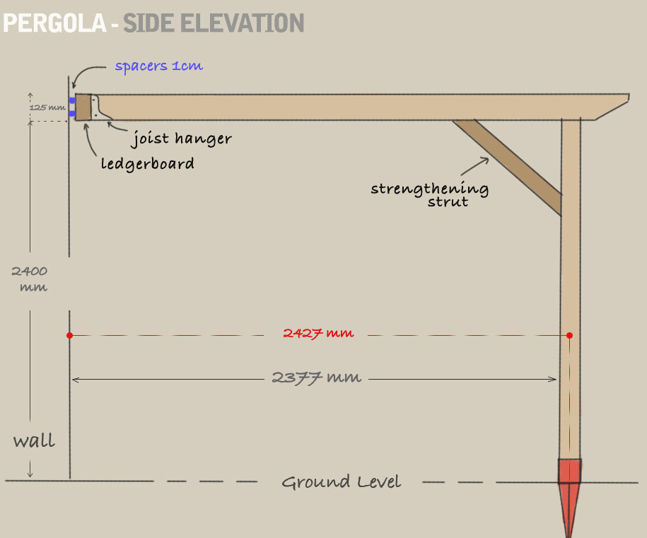
Figure 13 below shows how the pergola will look from the side elevation clearly illustrating the 1cm gap between the wall and the ledger board. As not all walls are flat, you are able to adapt the spacers by adding or taking them away to ensure a flat fit against the wall.
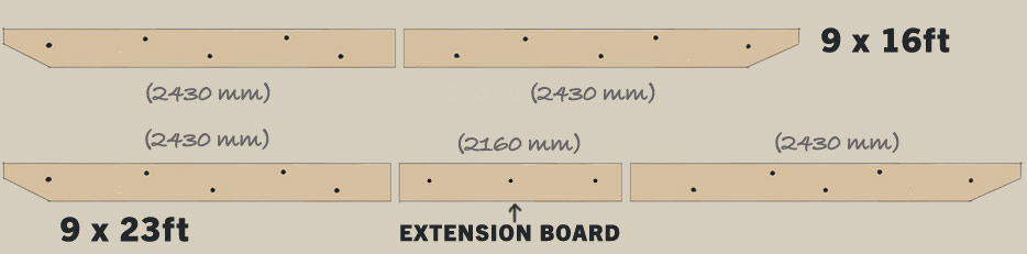
If you have ordered either of the two longer pergola modules, simply '&lsquo'butt up' the second ledger board on the 9ft x 16ft module or the 'extension' board plus second ledger board for the 9ft x 23ft module against the one already screwed into the wall making sure there is no gap between the boards and repeat the above process in Step 3. See Fig 13A below
(*NB these drawings are for representation purposes only and not to scale)